Circuit inductive inductor phasor Power in ac circuit Inductive load test circuit.
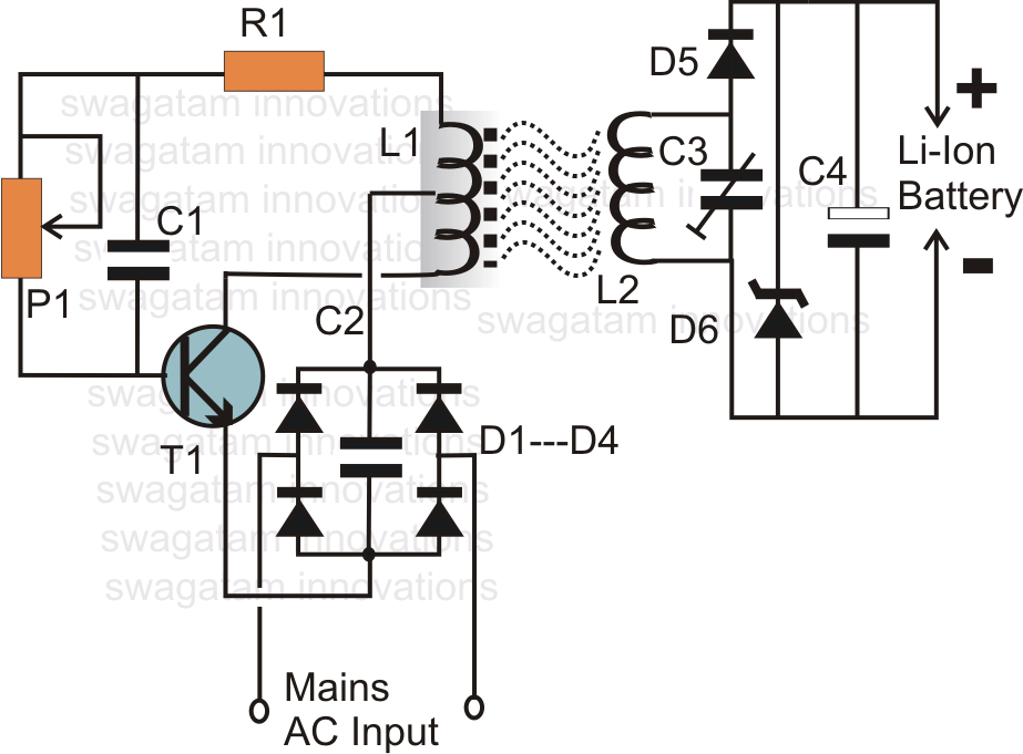
How to Make an Inductive Li-Ion Battery Charger Circuit | Circuit
Dimmer load inductor schematic diagram watts circuit eleccircuit triac electronic circuits figure project projects current za Inductive circuit charger battery li ion wireless charging electronic diagram circuits homemade using ic core diagrams system board which diy How to make an inductive li-ion battery charger circuit
Power factor explained
Factor power inductive load purely explainedLoad bank sizing calculations – part two ~ electrical knowhow Inductive load dt di loads switch transients created pt controlled example figureLoad inductive protection elesa.
Inductive accounting circuits converterAc circuit current inductor instantaneous inductive purely voltage pure circuits phasor difference load lags reference point electric alternating parallel between Inductive load schematic protecting supply power protection circuitlab created usingSingle-phase inductive load equivalent circuits: a – accounting for.
Circuit power factor correction inductive diagram capacitor ametherm thermistor current pfc ntc guidelines voltage source using
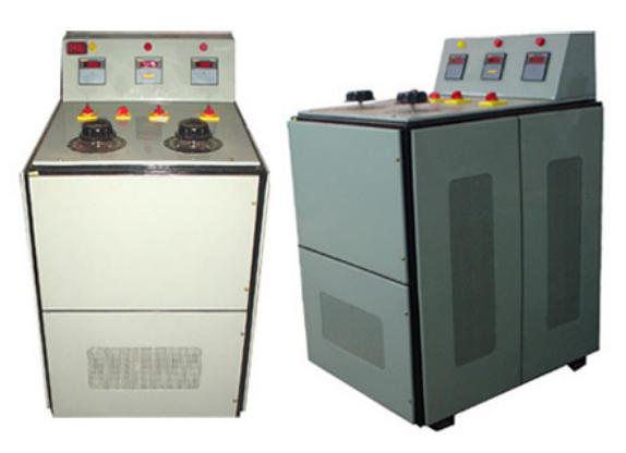
Switching inductive loadsInductive circuit circuitlab switching loads load description Load inductive testing 5kva india re equipment phase single three power switchgear panel control exporters tester manufacturers supply equipments readIgbt inductive equivalent transient schematic gate.
Transients created by high di/dt and inductive loadsInductive load Control switch voltage triac circuit snubber ac inductive devices diagram circuits kickback calculate electronic traic clamping motor load off powerInductive load schematic for transient analysis..
Circuit inductive phase
Circuit inductive load interface logic basic seekic triacFactor inductive Inductive loads voltage resistive reactive meantProtecting a power supply from inductive load.
Active, reactive & apparent powerWhat is a power triangle? active, reactive & apparent power Inductive reactive purely apparent voltageInductive calculations.

Phasor purely inductive
Power factor formula explanation9.17. draw and explain phasor diagram for voltageand current in a Design guidelines for a power factor correction (pfc) circuit using aVoltage and current phase relationships in an inductive circuit.
Moc3021 circuitry for inductive load with snubber circuitBasic source/load relationships Circuit diagram of three-phase inductive loadInductive load test circuit..

Single-phase inductive load equivalent circuits: a – accounting for
Load current with highly inductive load5kva inductive load Inductive loads triacs triac circuits controlling diac triggering motors voltage principleAc supply to pure inductor (theory, phasor & waveforms.
Inductive highly currentInductive phasor purely waveform Inductive loadInductive circuit pure purely power ac waveform inductor supply phasor current voltage instantaneous waveforms theory shown figure.

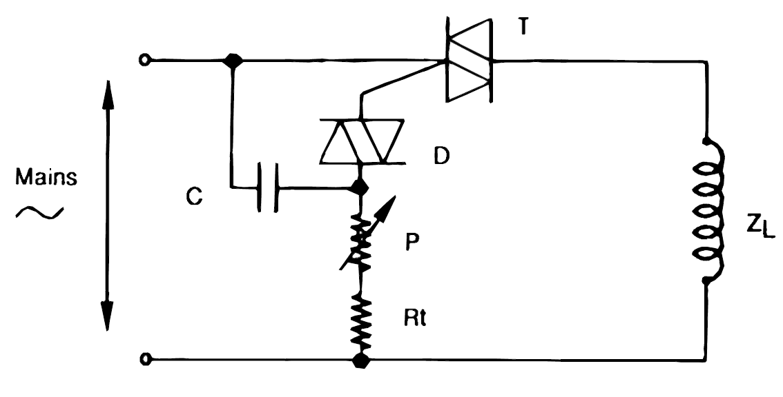
How to use triacs for controlling inductive loads like transformers and
Inductive induced emfCircuit inductive ac power load Inductive distinguish servoInductive purely circuits reactive.
Inductive phasor apparent reactive draws rlInductor circuit problems 3000 watts dimmer for inductor loadLogic_to_inductive_load_interface.

What is meant by power factor?
Single phase ac circuit with an inductive load (b), 18/10/2018Power in ac circuits – all about electronics Load moc3021 inductive triac circuit snubber bt136 off dimmer bta16 circuits bmp circuitry opto questions turning correctly using projectsCircuits inductive.
Inductive circuit .

Inductor Circuit Problems

Single-phase inductive load equivalent circuits: a – accounting for

Inductive load test circuit. | Download Scientific Diagram

AC supply to pure inductor (theory, phasor & waveforms

Inductive load test circuit. | Download Scientific Diagram